Digital Design and Computer Architecture 第三章归纳
0 前言
这一章学习Sequential Logic。首先学习几个基本元件,接着学习有限状态机,最后学习Timing分析。其中穿插了设计电路的原则和提高电路效率的方法。
从这篇笔记开始简化内容,一些直觉上认为不重要的内容就略过了。我是懒狗。
1 时序逻辑模块
Bistable Element
The fundamental building block of memory is a bistable element, an element with two stable states.
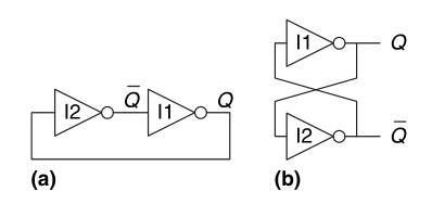
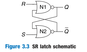
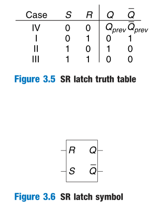
SR Latch
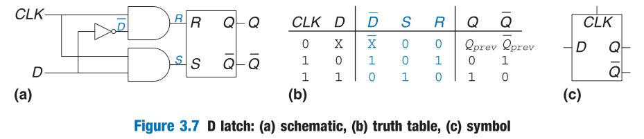
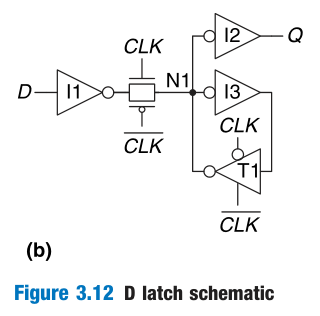
D Latch
The data input, D, controls what the next state should be. The clock input, CLK, controls when the state should change.
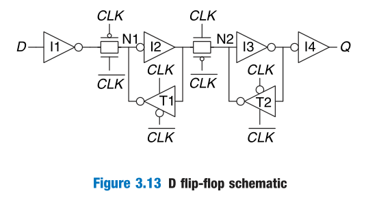
D Flip-Flop
A D flip-flop copies D to Q on the rising edge of the clock, and remembers its state at all other times.
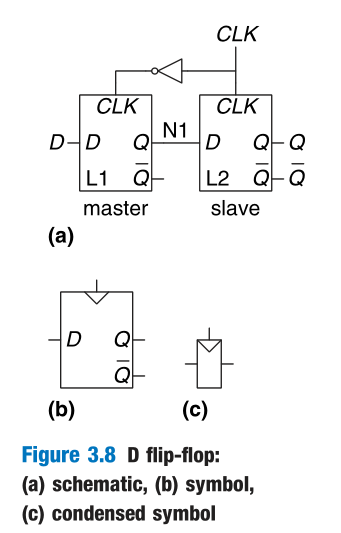
The term flip-flop or latch by itself usually refers to a D flip-flop or D latch, respectively, because these are the types most commonly used in practice.
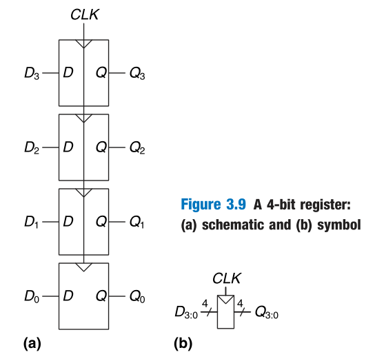
Register
An N-bit register is a bank of N flip-flops that share a common CLK input, so that all bits of the register are updated at the same time.
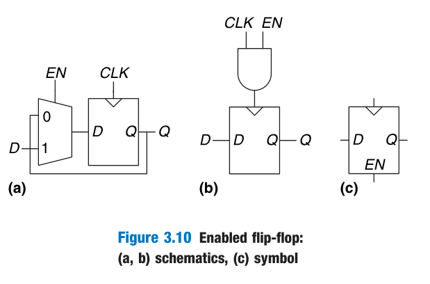
Enabled Flip-Flop
An enabled flip-flop adds another input called EN or ENABLE to determine whether data is loaded on the clock edge.
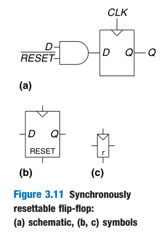
Resettable Flip-Flop
A resettable flip-flop adds another input called RESET. When RESET is FALSE, the resettable flip-flop behaves like an ordinary D flip-flop. When RESET is TRUE, the resettable flip-flop ignores D and resets the output to 0.
Such flip-flops may be synchronously or asynchronously resettable.
Transistors-Level Designs
2 设计原则
Definition of a Synchronous Sequential Circuit
A circuit is a synchronous sequential circuit if it consists of interconnected circuit elements such that
- Every circuit element is either a register or a combinational circuit
- At least one circuit element is a register
- All registers receive the same clock signal
- Every cyclic path contains at least one register.
Sequential circuits that are not synchronous are called asynchronous.
Asynchronous design in theory is more general than synchronous design, because the timing of the system is not limited by clocked registers. However, synchronous circuits have proved to be easier to design and use than asynchronous circuits
3 有限状态机
Definition
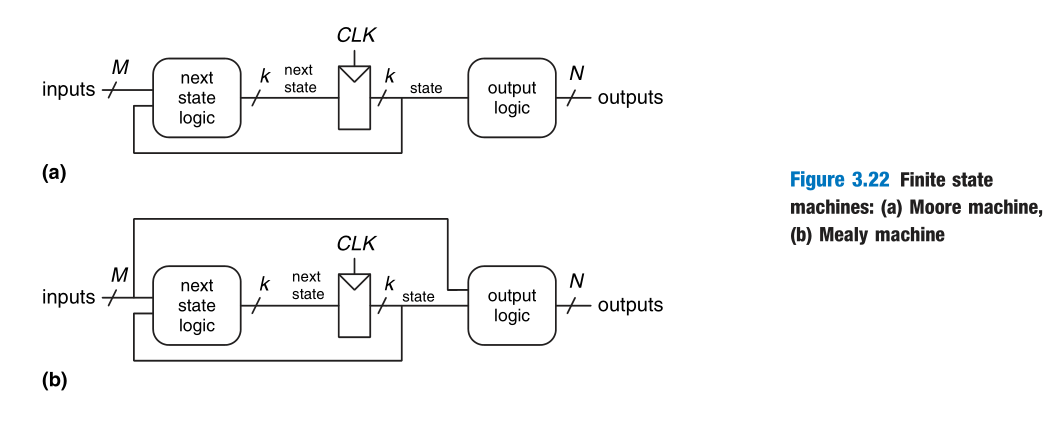
Synchronous sequential circuits can be drawn in the forms shown in Figure 3.22. These forms are called finite state machines (FSMs). They get their name because a circuit with k registers can be in one of a finite number ($2^k$) of unique states.
In Moore machines, the outputs depend only on the current state of the machine.
In Mealy machines, the outputs depend on both the current state and the current inputs.
Examples
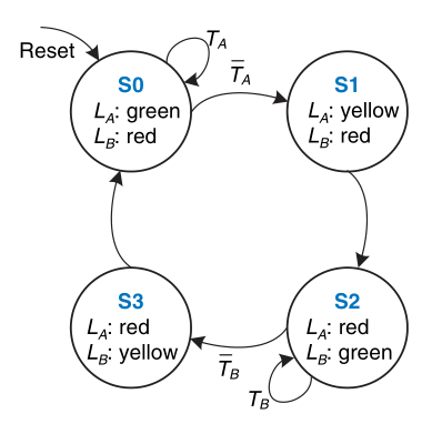
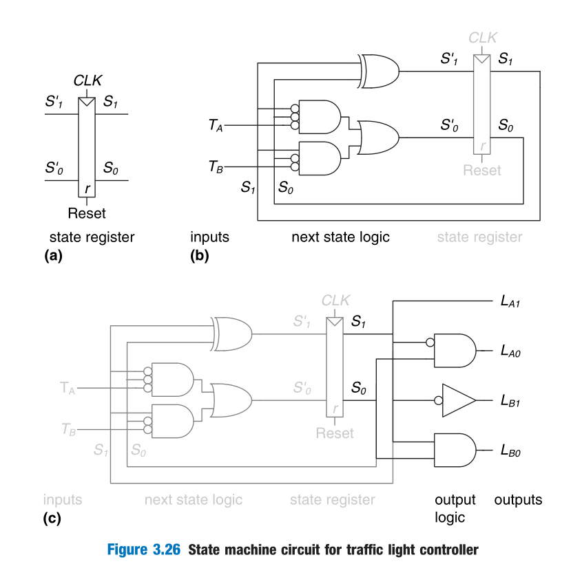
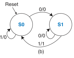
A controller for a traffic light (Moore Machine)
State transition diagram
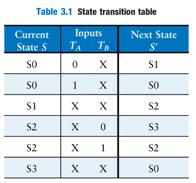
State transition table
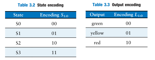
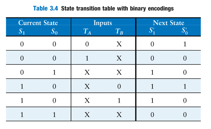
Encodings
Boolean Equations
$$
S’_1=\bar{S_1}S_0+S_1\bar{S_0}\bar{T_B}+S_1\bar{S_0}T_B\
S’_0=\bar{S_1}\bar{S_2}\bar{T_A}+S_1\bar{S_0}\bar{T_B}
$$Simplify it.
$$
S’_1=S_1\oplus S_0\
S’_0=\bar{S_1}\bar{S_2}\bar{T_A}+S_1\bar{S_0}\bar{T_B}
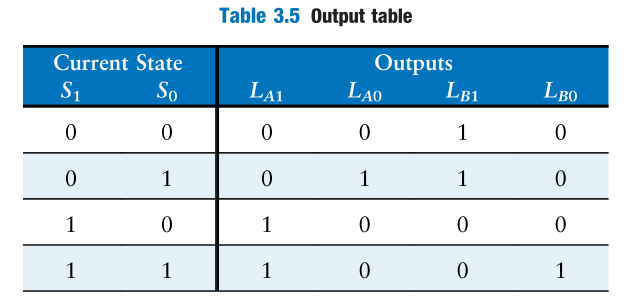
$$Similarly, get the output equations.
$$
L_{A1}=S_1\
L_{A0}=\bar{S_1}S_0\
L_{B1}=\bar{S_1}\
L_{B0}=S_1S_0
$$Draw the diagram
Mealy Machine
The snail crawls from left to right along a paper tape containing a sequence of 1’s and 0’s. On each clock cycle, the snail crawls to the next bit. The snail smiles when the last two bits that it has crawled over are, from left to right, 01. Design the FSM to compute when the snail should smile.
Factoring State Machines
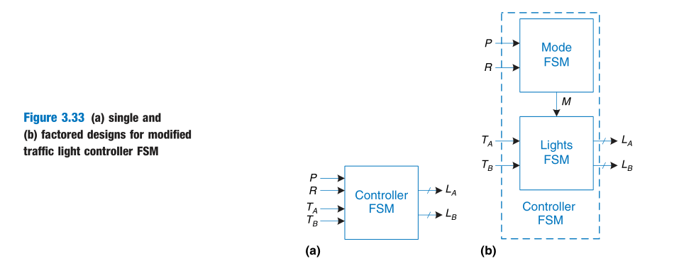
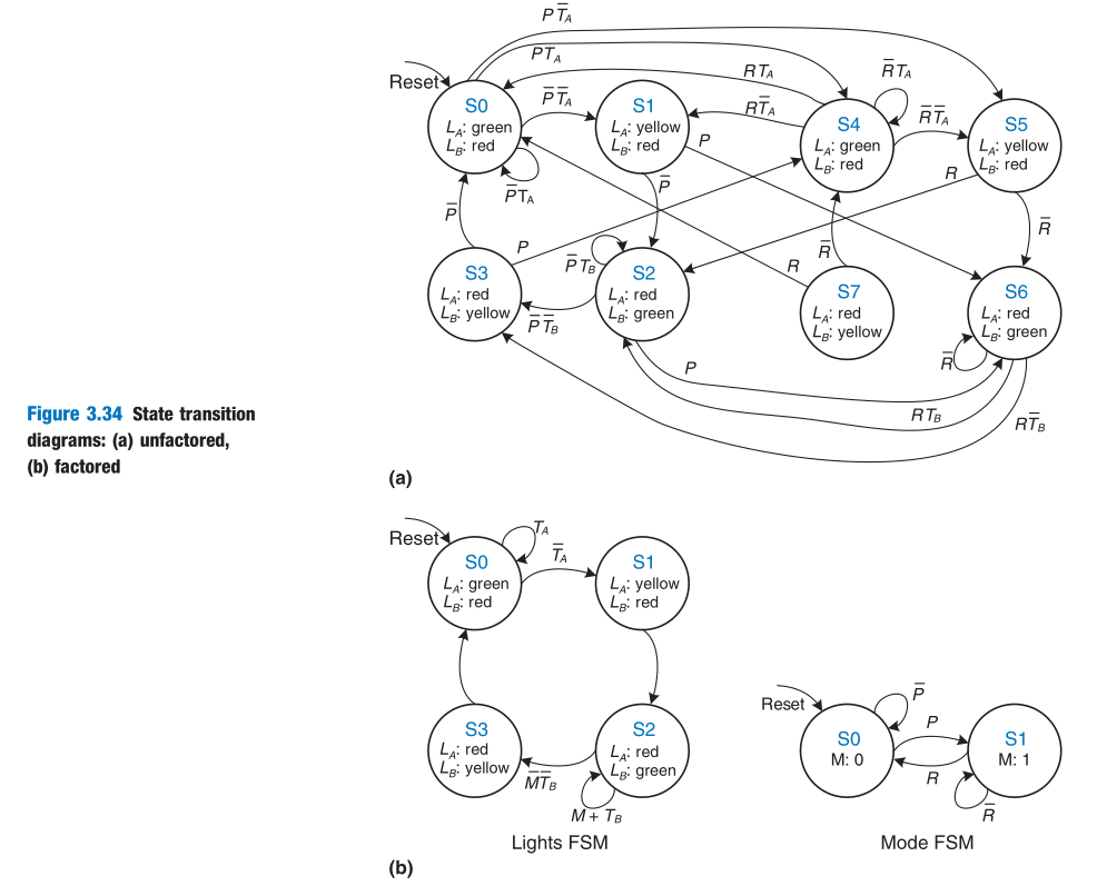
Encoding patterns
- With binary encoding, as was used in the traffic light controller example, each state is represented as a binary number.
- In one-hot encoding, a separate bit of state is used for each state.
A different choice would have resulted in a different circuit.
Deriving an FSM from a Schematic
Deriving the state transition diagram from a schematic follows nearly the reverse process of FSM design.
- Examine circuit, stating inputs, outputs, and state bits.
- Write next state and output equations.
- Create next state and output tables.
- Reduce the next state table to eliminate unreachable states.
- Assign each valid state bit combination a name.
- Rewrite next state and output tables with state names.
- Draw state transition diagram.
- State in words what the FSM does.
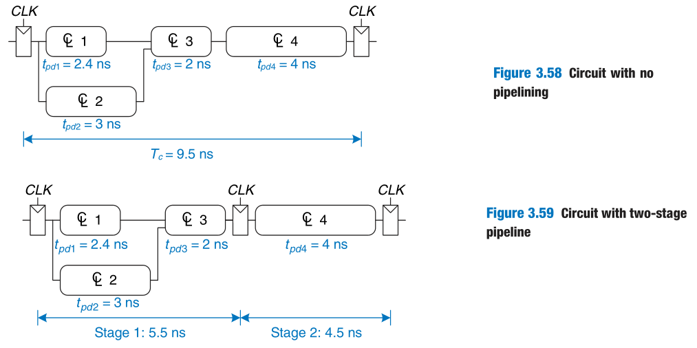
4 Timing
The Dynamic Discipline
The sum of the setup and hold times is called the aperture time of the circuit, because it is the total time for which the input must remain stable.

拓展阅读:
为什么会有建立时间(setup time)和保持时间(hold time)要求?
https://zhuanlan.zhihu.com/p/269274800
网页备份:
https://pan.baidu.com/s/1Rv0rat9MAu3v6H48-Mrc7A?pwd=fbbg
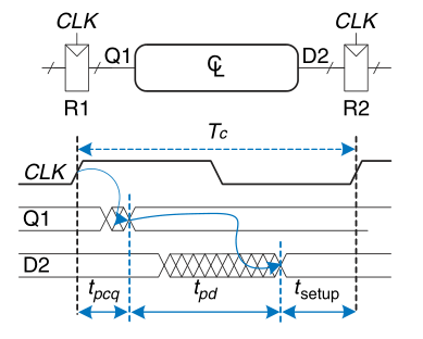
Setup Time Constraint
$$
t_{pd}\leq T_C-(t_{pcq}+t_{setup})
$$
This equation is called the setup time constraint or max-delay constraint.
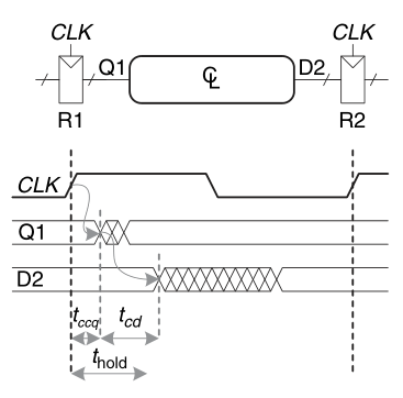
Hold Time Constraint
$$
t_{cd}\geq t_{hold}-t_{cq}
$$
This is also called the hold time constraint or min-delay constraint.
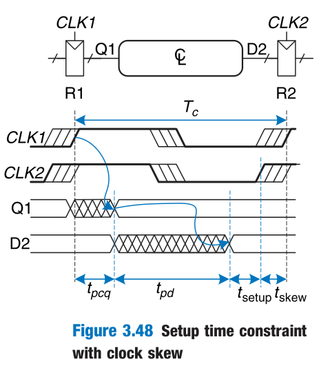
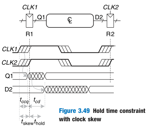
Clock Skew
In the previous analysis, we assumed that the clock reaches all registers at exactly the same time. In reality, there is some variation in this time. This variation in clock edges is called clock skew.
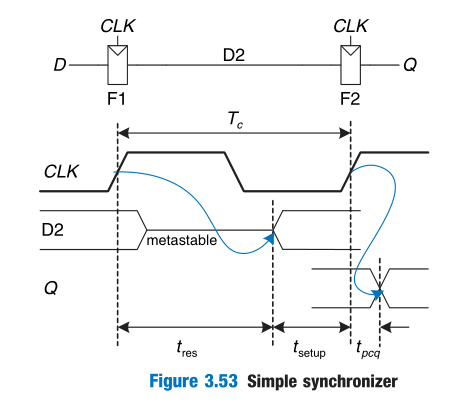
Metastability
When a flip-flop samples an input that is changing during its aperture, the output Q may momentarily take on a voltage between 0 and $V_{DD}$ that is in the forbidden zone. This is called a metastable state.
$$
P(t_{res}>t)=\frac{T_0}{T_c}e^{-\frac{t}{\tau}}
$$
公式推导略。
$T_c$ is the clock period, and $T_0$ and $\tau$ are characteristic of the flip-flop. The equation is valid only for t substantially longer than $t_{pcq}$.
Synchronizers
To guarantee good logic levels, all asynchronous inputs should be passed through synchronizers.
$$
P(failure)=\frac{T_0}{T_c}e^{-\frac{T_c-t_{setup}}{\tau}}
$$
If D changes N times per second:
$$
P(failure)/sec=N\frac{T_0}{T_c}e^{-\frac{T_c-t_{setup}}{\tau}}
$$
System reliability is usually measured in mean time between failures (MTBF):
$$
MTBF=\frac{1}{P(failure)/sec}=\frac{T_ce^{-\frac{T_c-t_{setup}}{\tau}}}{NT_0}
$$
5 Parallelism
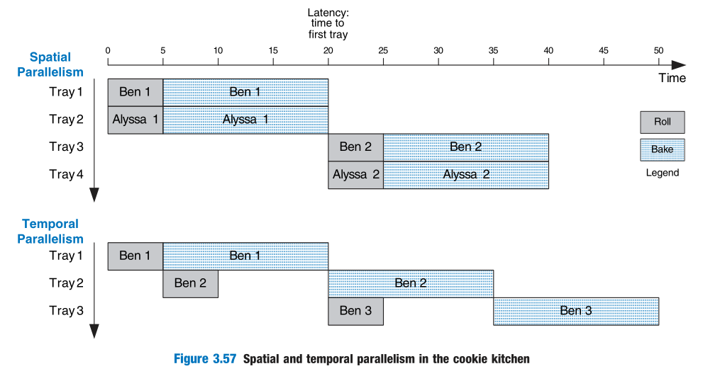
We define a token to be a group of inputs that are processed to produce a group of outputs.
The latency of a system is the time required for one token to pass through the system from start to end.
The throughput is the number of tokens that can be produced per unit time.
With spatial parallelism, multiple copies of the hardware are provided so that multiple tasks can be done at the same time.
With temporal parallelism, a task is broken into stages, like an assembly line. Multiple tasks can be spread across the stages. Temporal parallelism is commonly called pipelining.
Digital Design and Computer Architecture 第三章归纳
http://example.com/2022/08/03/Digital-Design-and-Computer-Architecture-第三章归纳/