0 前言 1 2 3 补充: 做完了教程平台里前三章的题,发现logisim里的多输入异或门和教材里描述的行为有差异。 教材里的多输入异或门起到奇偶校验的作用,而logisim里有单独的odd/even gates。
这章学习硬件描述语言,因为课程要求就只看Verilog的部分了。
突如其来的脑洞:
1 概念 Module A block of hardware with inputs and outputs is called a module.
Simulation and Synthesis During simulation, inputs are applied to a module, and the outputs are checked to verify that the module operates correctly. During synthesis, the textual description of a module is transformed into logic gates.
2 Examples & Idioms In our experience, the best way to learn an HDL is by example. HDLs have specific ways of describing various classes of logic; these ways are called idioms.
Combinational Logic sillyfunction 1 2 3 4 5 6 module sillyfunction(input logic a,b,c output logic y); assign y=~a&~b&~c| a&~b&~c| a&~b& c; endmodule
Bitwise Operators Inverters 1 2 3 4 module inv(input logic [3 :0 ] a, output logic [3 :0 ] y); assign y=~a; endmodule
Logic Gates 1 2 3 4 5 6 7 8 module gates(input logic [3 :0 ] a, b, output logic [3 :0 ] y1, y2, y3, y4, y5); assign y1=a&b; assign y2=a|b; assign y3=a^b; assign y4=~(a&b); assign y5=~(a|b); endmodule
Reduction Operators 1 2 3 4 module and8(input logic [7 :0 ] a, output logic y); assign y=&a; endmodule
Conditional Assignment 2:1 Multiplexer 1 2 3 4 5 module mux2(input logic [3 :0 ] d0, d1, input logic s, output logic [3 :0 ] y); assign y= s?d1:d0; endmodule
4:1 Multiplexer 1 2 3 4 5 module mux4(input logic [3 :0 ] d0,d1,d2,d3, input logic [1 :0 ] s, output logic [3 :0 ] y); assign y=s[1 ]?(s[0 ]?d3:d2):(s[0 ]?d1:d0); endmodule
Internal Variables Full Adder 1 2 3 4 5 6 7 8 module fulladder(input logic a, b, cin, output logic s, cout); logic p, g; assign p=a^b; assign g=a&b; assign s=p^cin; assign cout=g|(p&cin); endmodule
Z’s and X’s Tristate Buffers Tristate busses can have multiple drivers, so they should be declared as a net. Two types of nets in SystemVerilog are called tri and trireg.
1 2 3 4 5 module tristate(input logic [3 :0 ] a. input logic en, output tri [3 :0 ] y); assign y=en?a:4'bz ; endmodule
Bit Swizzling 1 assign y={c[2 :1 ],{3 {d[0 ]}},c[0 ],3'b101 }
Delays Logic Gates with Delays 1 2 3 4 5 6 7 8 9 10 'timescale 1 ns/1 ps module example(input logic a,b,c, output logic y); logic ab,bb,cb,n1,n2,n3; assign #1 {ab,bb,cb}=~{a,b,c}; assign #2 n1=ab&bb&cb; assign #2 n2=a&bb&cb; assign #2 n3=a&bb&c; assign #4 y=n1|n2|n3; endmodule
Structural Modeling Structural Model of 4:1 Multiplexers 1 2 3 4 5 6 7 8 module mux4(input logic [3 :0 ] d0, d1, d2, d3, input logic [1 :0 ] s, output logic [3 :0 ] y) logic [3 :0 ] low, high; mux2 lowmux(d0, d1, s[0 ], low); mux2 highmux(d2, d3, s[0 ], high); mux2 finalmux(low, high, s[1 ], y); endmodule
Accessing Parts of Busses 1 2 3 4 5 6 module mux2_8(input logic [7 :0 ] d0, d1. input logic s, output logic [7 :0 ] y); mux2 lsbmux(d0[3 :0 ], d1[3 :0 ], s, y[3 :0 ]); mux2 msbmux(d0[7 :4 ], d1[7 :4 ], s, y[7 :4 ]); endmodule
Sequential Logic Register 1 2 3 4 5 6 module flop(input logic clk, input logic [3 :0 ] d, output logic [3 :0 ] q); always_ff @(posedge clk) q<=d; endmodule
Resettable Register 1. Asynchronous
1 2 3 4 5 6 7 8 module flopr(input logic clk, input logic reset, input logic [3 :0 ] d, output logic [3 :0 ] q); always_ff @(posedge clk, posedge reset) if (reset) q<=4'b0 ; else q<=d; endmodule
2. Synchronous
1 2 3 4 5 6 7 8 module flopr(input logic clk, input logic reset, input logic [3 :0 ] d, output logic [3 :0 ] q); always_ff @(posedge clk) if (reset) q<=4'b0 ; else q<=d; endmodule
Enabled Register 1 2 3 4 5 6 7 8 9 module flopr(input logic clk, input logic reset, input logic en, input logic [3 :0 ] d, output logic [3 :0 ] q); always_ff @(posedge clk, posedge reset) if (reset) q<=4'b0 ; else if (en) q<=d; endmodule
Synchronizer 1 2 3 4 5 6 7 8 9 10 module sync(input clk, input logic d, output logic q); logic n1; always_ff @(posedge clk) begin n1<=d; q<=n1; end endmodule
More D Latch 1 2 3 4 5 6 module latch(input logic clk, input logic [3 :0 ] d, output logic [3 :0 ] q); always_latch if (clk) q<=d; endmodule
Inverter Using always 1 2 3 4 5 module inv(input logic [3 :0 ] a, output logic [3 :0 ] y); always_comb y=~a; endmodule
Full Adder Using always 1 2 3 4 5 6 7 8 9 10 11 module fulladder(input logic a, b, cin, output logic s, cout); logic p, g; always_comb begin p=a^b; g=a&b; s=p^cin; cout=g|(p&cin); end endmodule
Seven-Segment Display Decoder 1 2 3 4 5 6 7 8 9 10 11 12 13 14 15 16 17 18 19 module sevenseg(input logic [3 :0 ] data, output logic [6 :0 ] segments); always_comb case (data) 0 : segments = 7'b111_1110 ; 1 : segments = 7'b011_0000 ; 2 : segments = 7'b110_1101 ; 3 : segments = 7'b111_1001 ; 4 : segments = 7'b011_0011 ; 5 : segments = 7'b101_1011 ; 6 : segments = 7'b101_1111 ; 7 : segments = 7'b111_0000 ; 8 : segments = 7'b111_1111 ; 9 : segments = 7'b111_0011 ; default : segments = 7'b000_0000 ; endcase endmodule
3:8 Decoder 1 2 3 4 5 6 7 8 9 10 11 12 13 14 15 module decoder3_8(input logic [2 :0 ] a, output logic [7 :0 ] y); always_comb case (a) 3'b000 : y = 8'b00000001 ; 3'b001 : y = 8'b00000010 ; 3'b010 : y = 8'b00000100 ; 3'b011 : y = 8'b00001000 ; 3'b100 : y = 8'b00010000 ; 3'b101 : y = 8'b00100000 ; 3'b110 : y = 8'b01000000 ; 3'b111 : y = 8'b10000000 ; default : y = 8'bxxxxxxxx ; endcase endmodule
Priority Circuit 1 2 3 4 5 6 7 8 9 module priorityckt(input logic [3 :0 ] a, output logic [3 :0 ] y); always_comb if (a[3 ]) y <= 4'b1000 ; else if (a[2 ]) y <= 4'b0100 ; else if (a[1 ]) y <= 4'b0010 ; else if (a[0 ]) y <= 4'b0001 ; else y <= 4'b0000 ; endmodule
Priority Circuit Using Don’t Cares 1 2 3 4 5 6 7 8 9 10 11 module priority_casez(input logic [3 :0 ] a, output logic [3 :0 ] y); always_comb casez (a) 4'b1 ???: y <= 4'b1000 ; 4'b01 ??: y <= 4'b0100 ; 4'b001 ?: y <= 4'b0010 ; 4'b0001 : y <= 4'b0001 ; default : y <= 4'b0000 ; endcase endmodule
Finite State Machines Divide-By-3 Finite State Machines 1 2 3 4 5 6 7 8 9 10 11 12 13 14 15 16 17 18 19 20 module divideby3FSM(input logic clk, input logic reset, output logic y); typedef enum logic [1 :0 ]{S0, S1, S2} statetype; statetype [1 :0 ] state, nextstate; always_ff @(posedge clk, posedge reset) if (reset) state<=S0; else state<=nextstate; always_comb case (state) S0: nextstate<=S1; S1: nextstate<=S2; S2: nextstate<=S0; default :nextstate<=S0; endcase assign y=(state == S0); endmodule
Pattern Recognizer Moore FSM 1 2 3 4 5 6 7 8 9 10 11 12 13 14 15 16 17 18 19 20 21 22 23 24 module patternMoore(input logic clk, input logic reset, input logic a, output logic y); typedef enum logic [1 :0 ]{S0,S1,S2} statetype; statetype state, nextstate; always_ff @(posedge clk,posedge reset) if (reset) state <=S0; else state<=nextstate; always_comb case (state) S0:if (a) nextstate=S0; else nextstate=S1; S1:if (a) nextstate=S2; else nextstate=S1; S2: if (a) nextstate = S0; else nextstate = S1; default : nextstate = S0; endcase assign y = (state == S2); endmodule
Pattern Recognizer Mealy FSM 1 2 3 4 5 6 7 8 9 10 11 12 13 14 15 16 17 18 19 20 21 module patternMoore(input logic clk, input logic reset, input logic a, output logic y); typedef enum logic {S0,S1} statetype; statetype state, nextstate; always_ff @(posedge clk,posedge reset) if (reset) state <=S0; else state<=nextstate; always_comb case (state) S0: if (a)nextstate=S0; else nextstate=S1; S1: if (a)nextstate=S0; else nextstate=S1; default : nextstate=S0; endcase assign y=(a & state==S1); endmodule
Parameterized Modules Parameterized N-Bit 2:1 Multiplexers 1 2 3 4 5 6 7 8 9 10 11 12 13 14 15 16 module mux2 #(parameter width=8 ) (input logic [width-1 :0 ]d0,d1, input logic s, output logic [width-1 :0 ] y); assign y=s?d1:d0; endmodule module mux4_12(input logic [11 :0 ] d0,d1,d2,d2, input logic [1 :0 ] s, output logic [11 :0 ] y); logic [11 :0 ] low,hi; mux2 #(12) lowmux(d0,d1,s[0],low) ; mux2 #(12) himux(d2,d3,s[0],hi) ; mux2 #(12) outmux(low,hi,s[1],y) ; endmodule
1 2 3 4 5 6 7 8 9 10 11 12 13 14 module andN #(parameter width=8 ) (input logic [width-1 :0 ]a, output logic y); genvar i; logic [width-1 :0 ] x; generate assign x[0 ]=a[0 ]; for (i=1 ;i<width;i=i+1 )begin : forloop assign x[i]=a[i]&x[i-1 ]; end endgenerate assign y=x[width-1 ]; endmodule
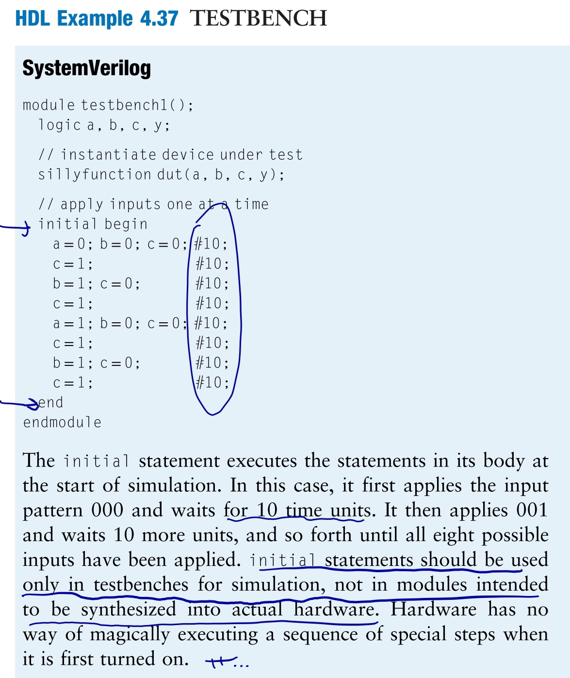
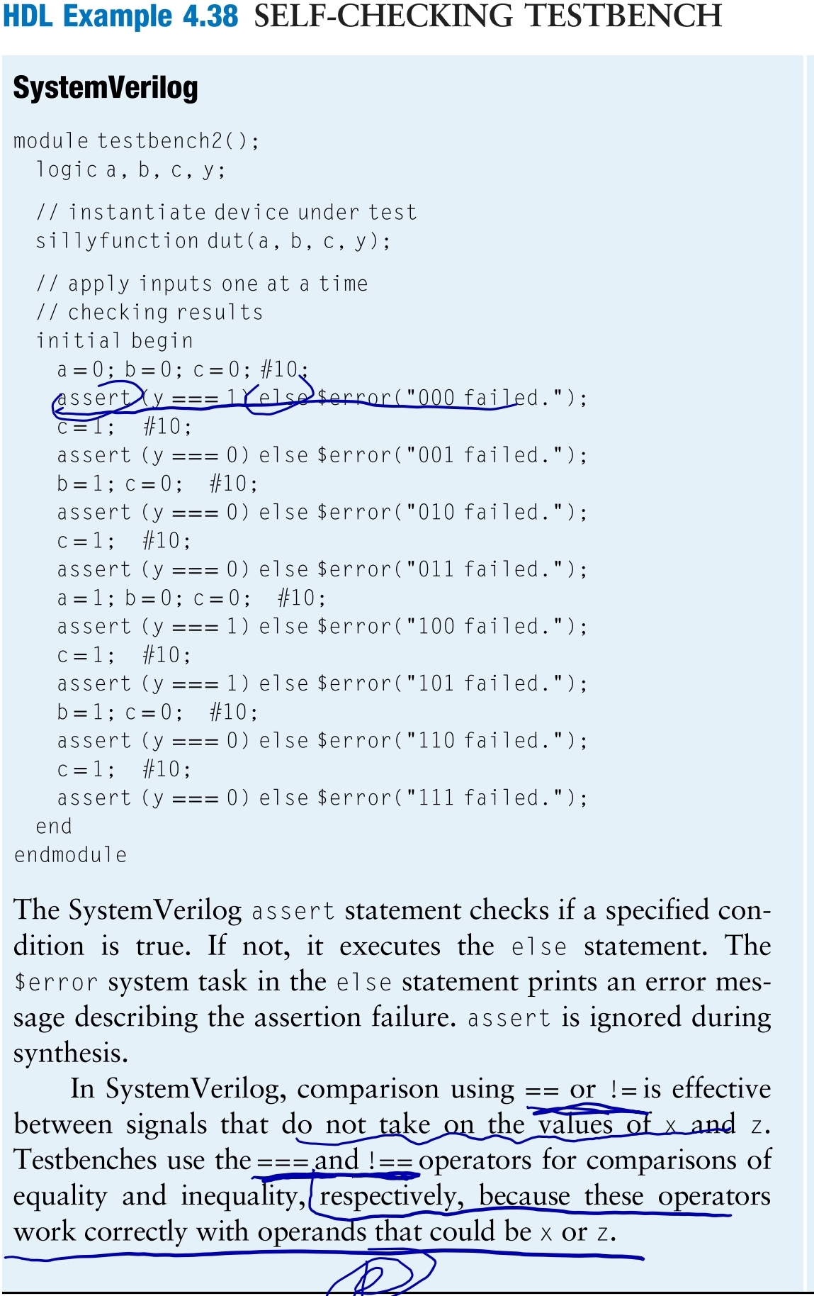
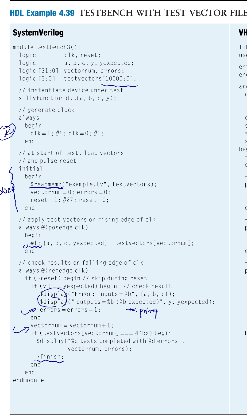
Testbenches 累了,懒得手打了。
3 准则
Use always_ff @(posedge clk) and nonblocking assignments to model synchronous sequential logic.
Use continuous assignments to model simple combinational logic.
Use always_comb and blocking assignments to model more complicated combinational logic where the always statement is helpful.
Do not make assignments to the same signal in more than one always statement or continuous assignment statement.
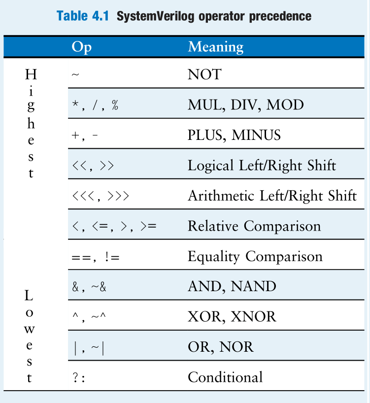
4 语法查阅 运算符优先级表
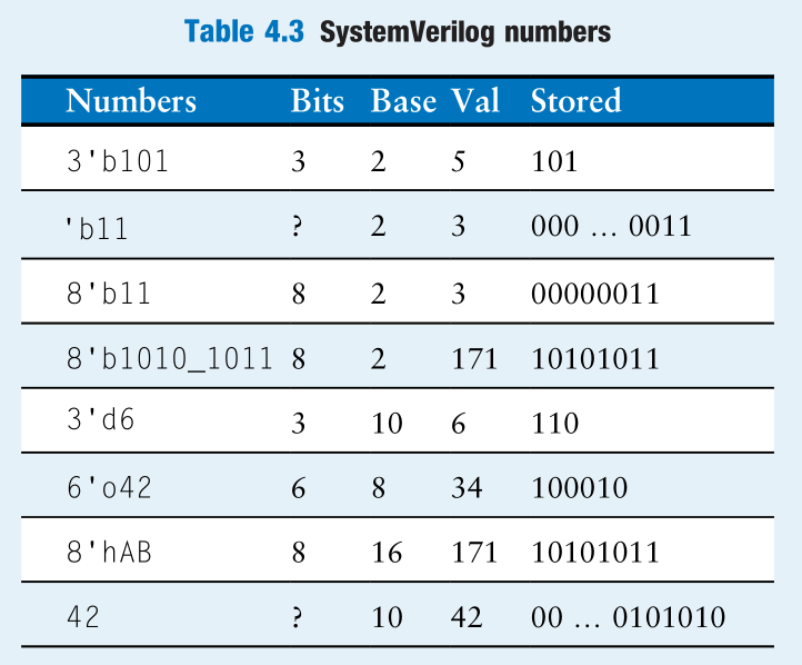
常数 The format for declaring constants is N’Bvalue, where N is the size in bits, B is a letter indicating the base, and value gives the value.
An exception is that ‘0 and ‘1 are SystemVerilog idioms for filling a bus with all 0s and all 1s, respectively.