Digital-Design-and-Computer-Architecture-第五章归纳
0 前言
这一章学习了小数的二进制表示,一些更复杂的blocks,对之前的很多内容做了拓展和补充。
1 Number Systems
Fixed-Point Number
Fixed-point notation has an implied binary point between the integer and fraction bits, analogous to the decimal point between the integer and fraction digits of an ordinary decimal number.
There is no way of knowing the existence of the binary point except through agreement of those people interpreting the number.
Floating-Point Number Systems
Sign: 0+, 1-.
Biased Exponent: Original exponent +127. (32bit)
Fraction: The first bit of mantissa is erased.

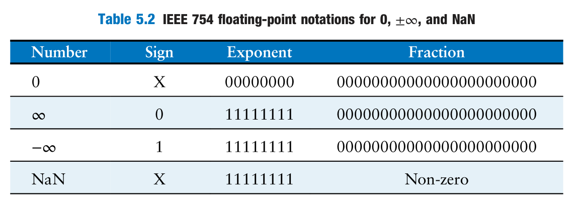
Special Cases
Formats

Rounding
The rounding modes are: round down, round up, round toward zero, and round to nearest. The default rounding mode is round to nearest.
A number overflows to $\pm \infty$ when its magnitude is too large to be represented. Likewise, a number underflows to $0$ when it is too tiny to be represented.
Floating-Point Addition
- Extract exponent and fraction bits.
- Prepend leading 1 to form the mantissa.
- Compare exponents.
- Shift smaller mantissa if necessary.
- Add mantissas.
- Normalize mantissa and adjust exponent if necessary.
- Round result.
- Assemble exponent and fraction back into floating-point number.
2 Arithmetic Circuits
Addition
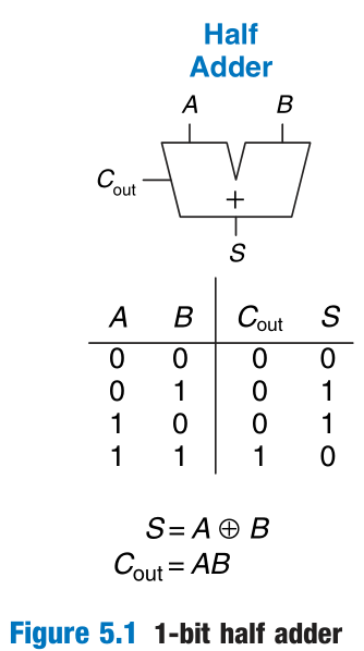
Half Adder
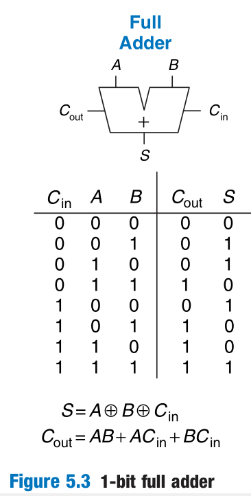
Full Adder
Ripple Carry Adder

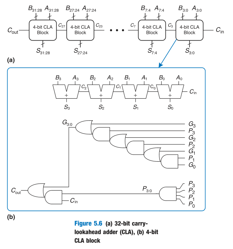
Carry Lookahead Adder (CLA)
$$
G_i=A_iB_i\
P_i=A_i+B_i\
C_i=G_i+P_iC_{i-1}
$$
As for multiple-bit occasions,
$$
G_{i:j}=C_i\
P_{i:j}=\prod_{k=i}^jP_k\
C_{i:j}=G_{i:j}+P_{i:j}C_{in}
$$
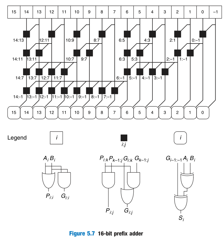
Prefix Adder
They first compute G and P for pairs of columns, then for blocks of 4, then for blocks of 8, then 16, and so forth until the generate signal for every column is known. The sums are computed from these generate signals.
Subtraction
Subtraction is almost as easy: flip the sign of the second number, then add.
Comparators
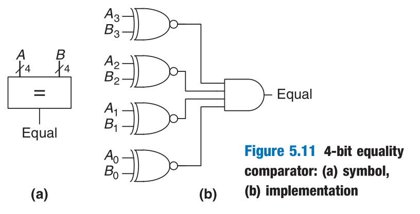
Equality Comparator
Magnitude Comparator
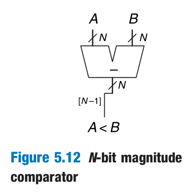
Magnitude comparison is usually done by computing A − B and looking at the sign (most significant bit) of the result as shown in Figure 5.12.
Arithmetic/Logical Unit (ALU)
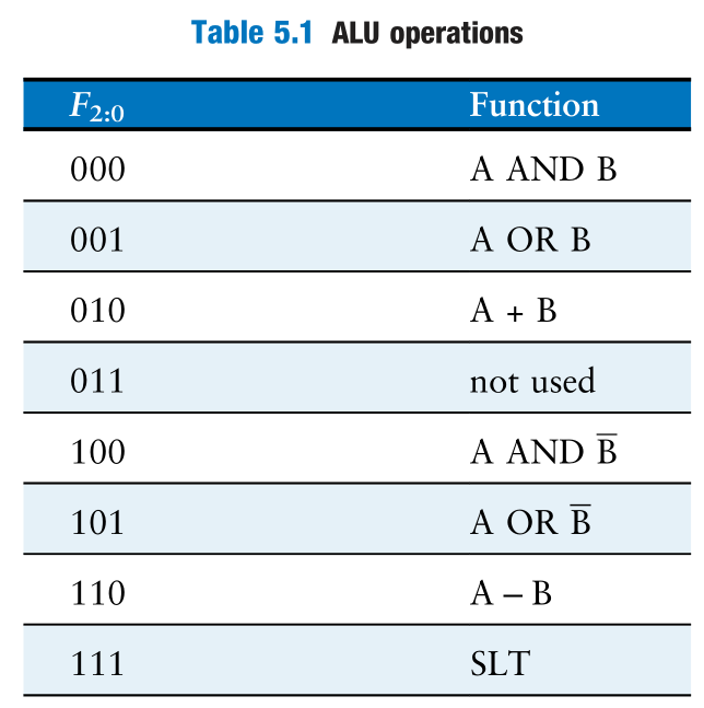
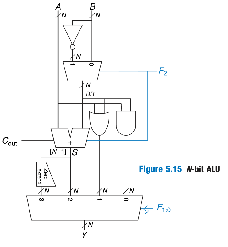
Shifters
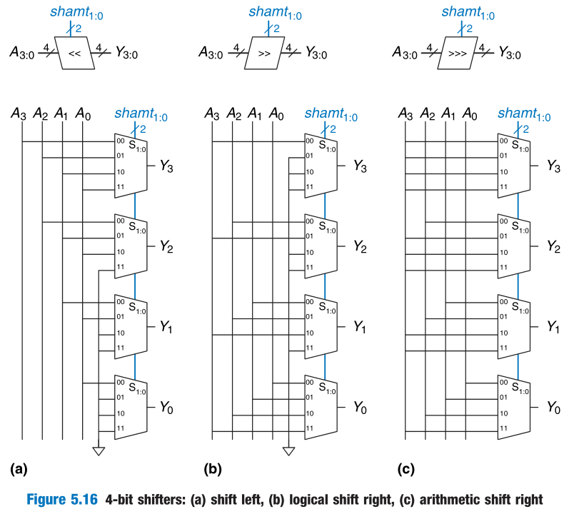
Multiplication
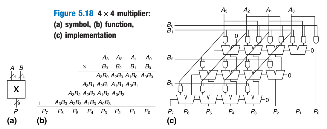
Division
略
3 Sequential Building Blocks
Counter
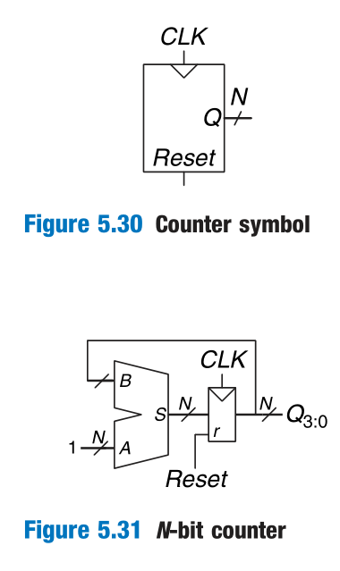
1 | module counter #(parameter N=8) |
Shift Register
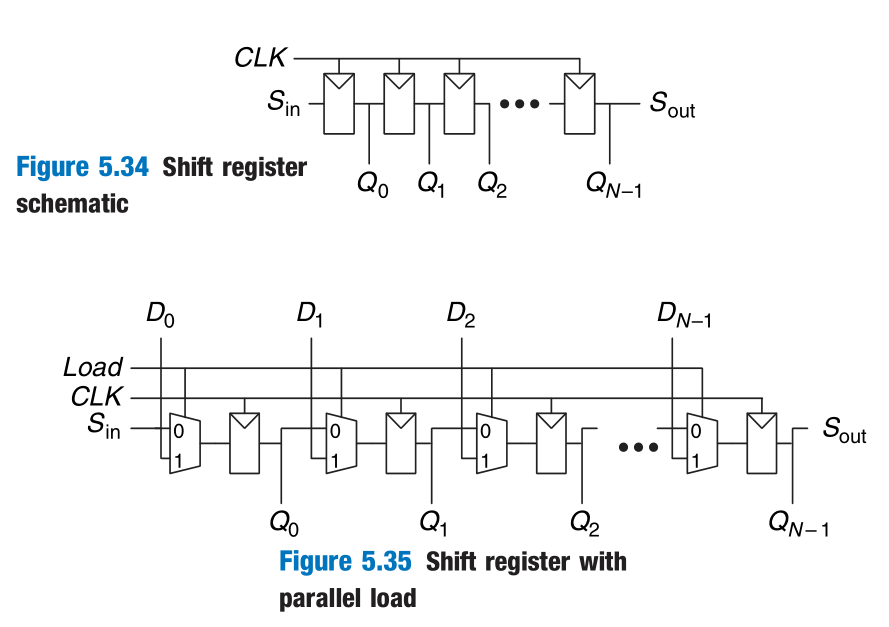
1 | module shiftReg #(parameter N=8) |
Scan Chains
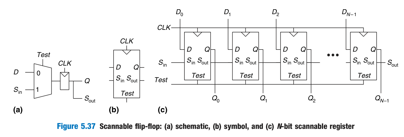
4 Memory Arrays
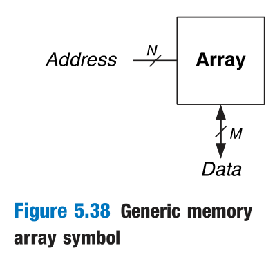
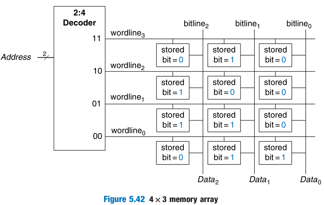
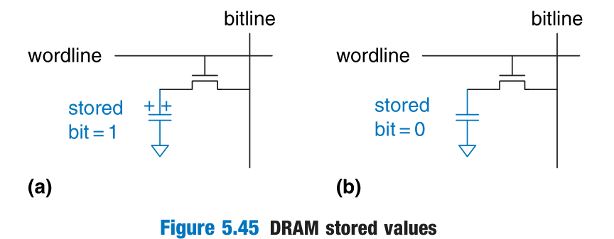
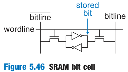
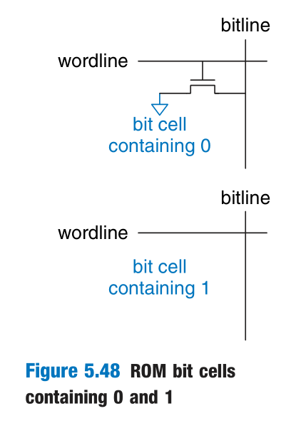
Memories are classified based on how they store bits in the bit cell. The broadest classification is random access memory (RAM) versus read only memory (ROM). RAM is volatile, meaning that it loses its data when the power is turned off. ROM is nonvolatile, meaning that it retains its data indefinitely, even without a power source.
RAM and ROM received their names for historical reasons that are no longer very meaningful.
DRAM
SRAM
ROM
1 | module RAM #(parameter N=6, M=32) |
PROM
Fuse-programmable ROM
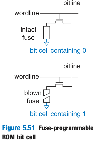
Memory arrays used to perform logic are called lookup tables (LUTs).
5 Logic Arrays
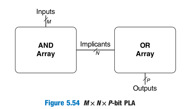
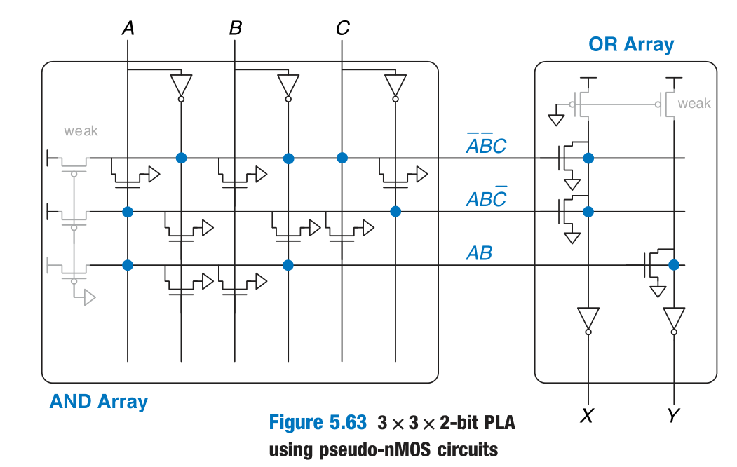
PLA
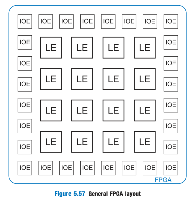
FPGA
FPGAs are built as an array of configurable logic elements (LEs), also referred to as configurable logic blocks (CLBs). Each LE can be configured to perform combinational or sequential functions.
The LEs are surrounded by input/output elements (IOEs) for interfacing with the outside world.
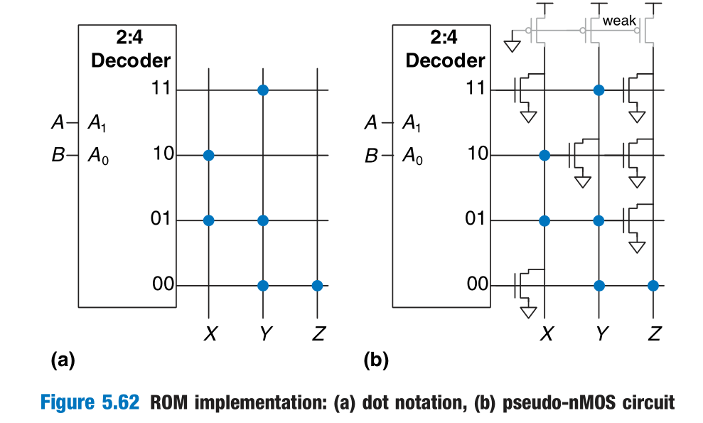
6 Array Implementations
Refer to Chapter 1.
Digital-Design-and-Computer-Architecture-第五章归纳
http://example.com/2022/09/03/Digital-Design-and-Computer-Architecture-第五章归纳/
